RotorDynamics — Credible Synthetic Data for Rotating Machinery
Condition monitoring and predictive maintenance run on data, and the data that matters most — a machine with a fault, at a known severity, in a known location — is the data nobody has. Real faults are rare, expensive to wait for, and almost never labelled. RotorDynamics is a Modelica library built by Model Based Innovation for one purpose:
to create credible synthetic data for fault detection in rotating machinery and gearboxes.
The library models shaft lines, rotors, rolling-element, plain and fluid-film bearings, couplings, housings and foundations, and the gearing that connects them — spur, helical, double-helical, internal, bevel, spiral-bevel, hypoid, crossed-helical, worm, rack-and-pinion and complete planetary stages. On top of that physics sit the fault models: bearing race defects, spalled teeth, eccentric wheels, misaligned couplings, planet-bearing faults and rotor instabilities. Run the same machine healthy and faulted, and you get vibration, displacement, speed and torque signals whose fault content is known exactly — ready for training and benchmarking diagnostic algorithms, or as the physics core of a digital twin.
What sets RotorDynamics apart is not the component list. It is that every claim the library makes about its own physics is checked, recorded and traceable — see Verification & Validation below.
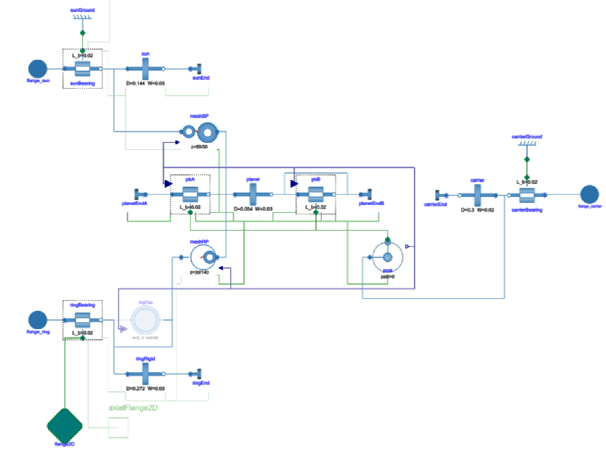

Every component's equations are in the source, documented next to the checks that verify them. Nothing is hidden in a solver black box.

A single rotor-dynamics connector carries two lateral translations, two bending slopes and the shaft angle — with an optional axial companion flange for thrust.

Bridges to the Modelica Standard Library's Rotational, Translational and MultiBody packages, so motors, brakes, clutches and flexible foundations plug straight in.
What You Can Model

Rigid, Euler-Bernoulli flexible and torsionally compliant shafts, shafts with distributed mass, eccentric and gyroscopic rotors, and laminated rotors with hysteretic core interfaces.

Rolling-element bearings with a Hertz-impact fault model, contact angle and friction; Coulomb plain bearings; 8-coefficient hydrodynamic bearings with Petroff friction and an Ocvirk short-bearing geometry mode; thrust bearings; horizontal and vertical housings.

Compliant involute meshes — external and internal, spur and helical, with profile shift, mesh stiffness variation, transmission error, backlash, tooth-flank friction and localized tooth damage — plus bevel, hypoid, crossed-helical, worm and rack-and-pinion meshes.

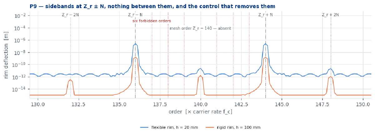
A composed planetary stage with carrier posts, in-phase or sequentially phased planets, planet bearings, and a flexible ring gear whose rim bending produces the modulation sidebands a ring accelerometer actually sees.

Displacement, slope, speed, angle and acceleration sensors on the shaft, and displacement and acceleration sensors on the housing — the channels a real monitoring system records.

Gravity is a vector resolved per component: horizontal, vertical, inclined and right-angled shaft lines in one model, with an axial load path that carries a vertical machine's weight.
Fault Models for Diagnostic Data
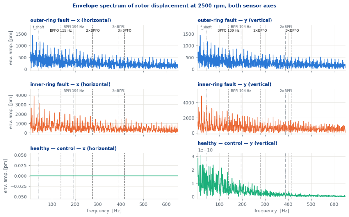
The bearing-fault model implements the ball-impact formulation of Ishibashi, Han and Kawai (Modelica Conference 2017) and extends it considerably. Impacts are triggered by shaft angle, not by time, so the impulse train stays phase-locked through a run-up — the ratio of impact spacing to ball-pass period is 1 at every impact to better than 10⁻⁶. The contact pulse follows the Hertzian profile and transfers exactly the momentum an elastic collision must.
The result is the signature an envelope-based diagnostic keys on: lines at the ball-pass frequencies (BPFO, BPFI) and their harmonics, shaft-speed sidebands for an inner-race defect — and nothing at those lines in the healthy control run.
Other fault and excitation mechanisms in the library:
- Spalled teeth, eccentric wheels and runout on any gear mesh
- Planet-bearing faults on a carrier that moves
- Coupling offset and angular misalignment
- Internal-damping (Newkirk–Kimball) whirl instability
- Angle-synchronous motor torque ripple
- Belt pull and spring loads for test-rig reconstructions
Example Applications
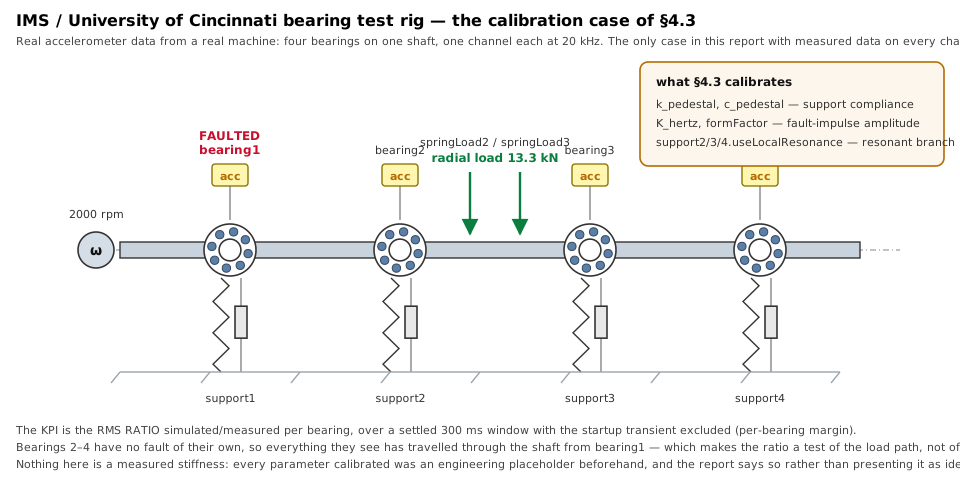
IMS Bearing Run-to-Failure Rig
A reconstruction of the IMS / University of Cincinnati endurance rig (NASA PCoE dataset): four bearings on one shaft, a 13.3 kN radial preload, one accelerometer per housing. The pedestal, shaft mass and fault impulse were calibrated against the real accelerometer recordings, bringing the simulated-to-measured RMS ratio from 96×–737× down to 0.84×–1.03× across all four channels. The calibration also found that one bearing needed an extra degree of freedom — an outer-ring resonance near the dataset’s own BPFO — rather than a retuned damper.
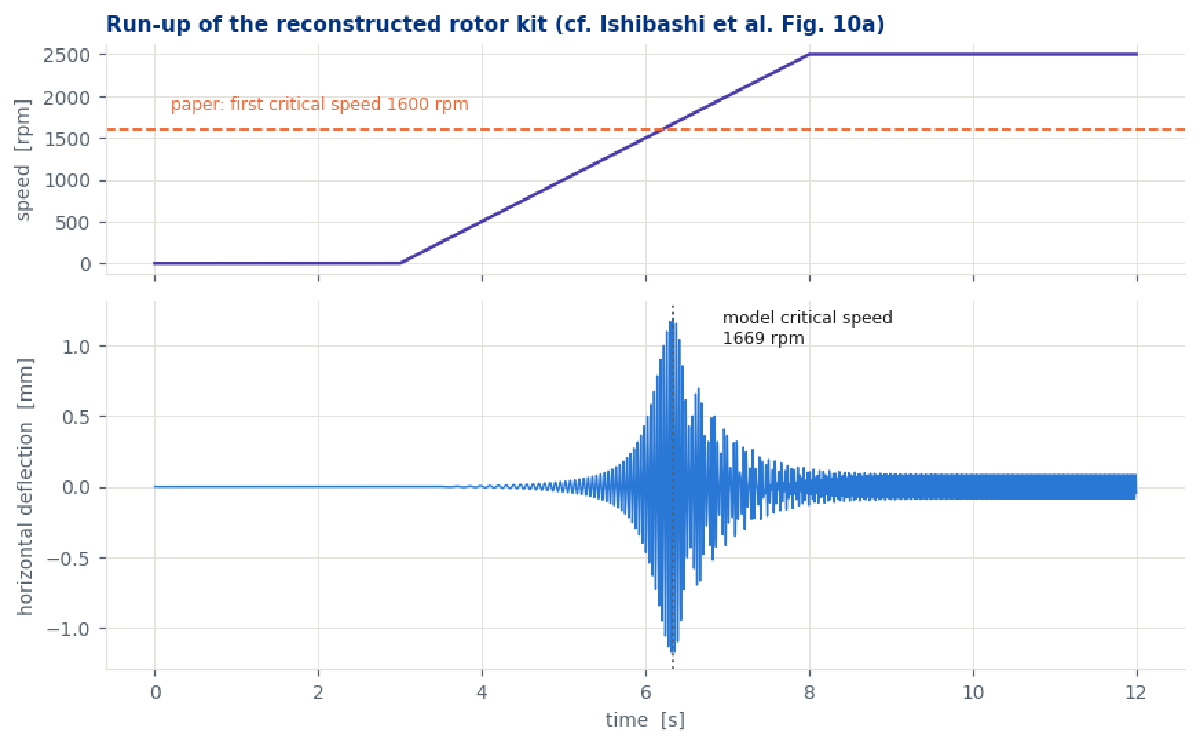
Laboratory Rotor Kit
The rotor kit from the original paper, rebuilt from its published parameter table. With no parameter tuned, the model predicts the first critical speed at 1669 rpm against the paper’s 1600 rpm (+4.3 %) at the paper’s own run-up rate, and within about 1 % once the sweep-rate bias is removed. The one parameter the paper never reports — bearing radial stiffness — moves the answer by less than 0.1 % over two decades.
Planetary Gearbox with a Flexible Ring
Why does a fixed accelerometer on a planetary ring see sidebands at all? On a rigid ring, equally spaced planet forces cancel and there is nothing to measure. RotorDynamics models the ring rim as a flexible structure, so the sidebands are an output of the physics rather than of an assumed weighting window. The model reproduces the published sideband pattern (Inalpolat 2009, case i) from first principles — and the control run with a stiff rim correctly loses them. A digital twin of the public NLR Gearbox Reliability Collaborative 750 kW gearbox is under way on the same components.
Right-Angle Spiral-Bevel Drive
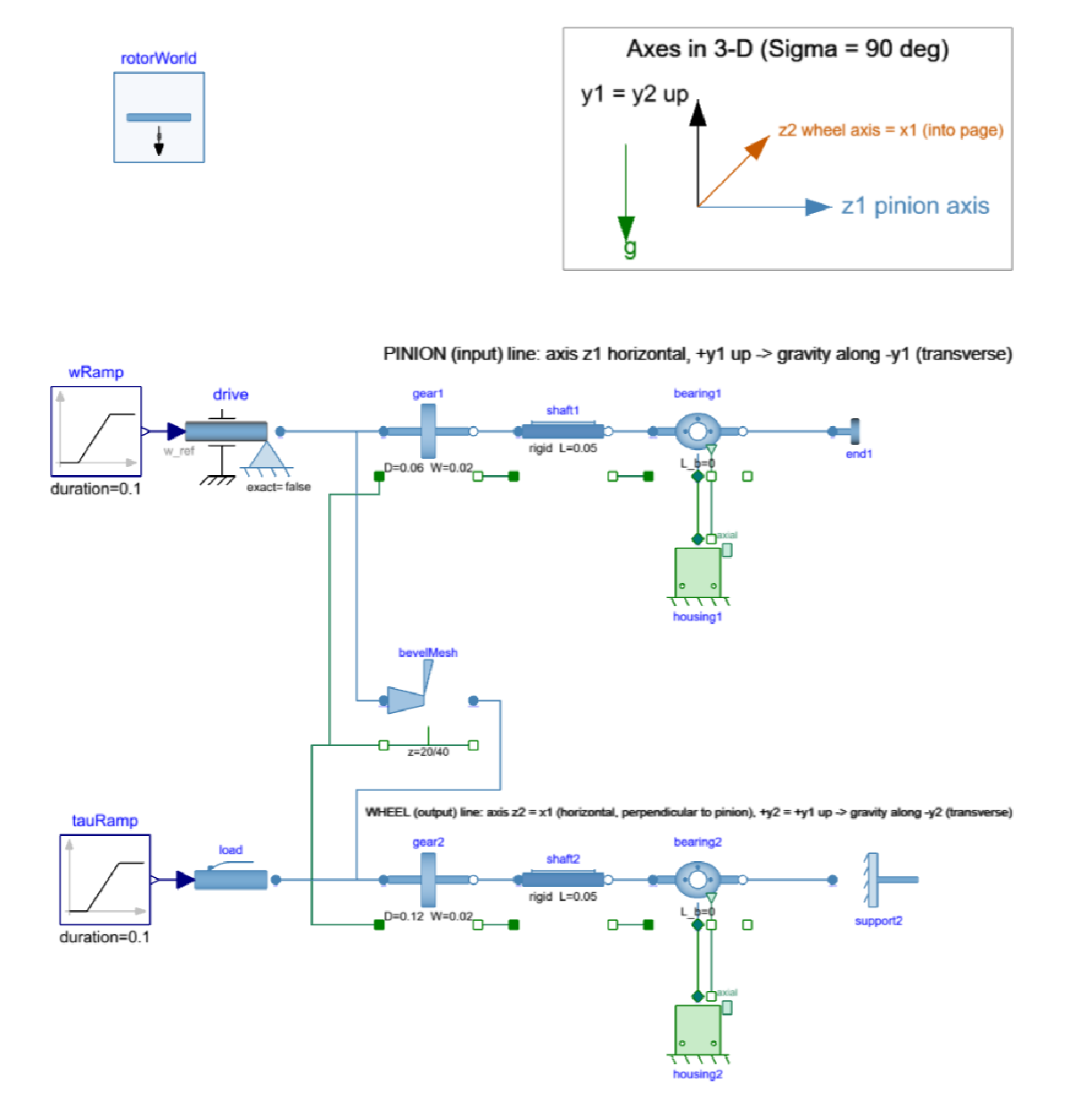
A complete right-angle drive with its thrust reacted where a real gearbox reacts it, in the locating bearings. This example also carries a machine-readable context of use: the quantities of interest for a specific engineering task, declared on the model itself, so the tooling can check before a single simulation runs whether the components used can deliver them.
Verification and Validation in Depth
Most simulation libraries ship with examples. RotorDynamics ships with a credibility report: a Jupyter notebook that runs every check live against a Modelon Impact workspace and regenerates every number, table and figure from scratch. Nothing in it is transcribed. It follows the Credible Modeling Process (the model-level tier of the prostep ivip SmartSE Simulation Credibility Assessment framework) and uses ASME VVUQ 1-2022 terminology throughout.
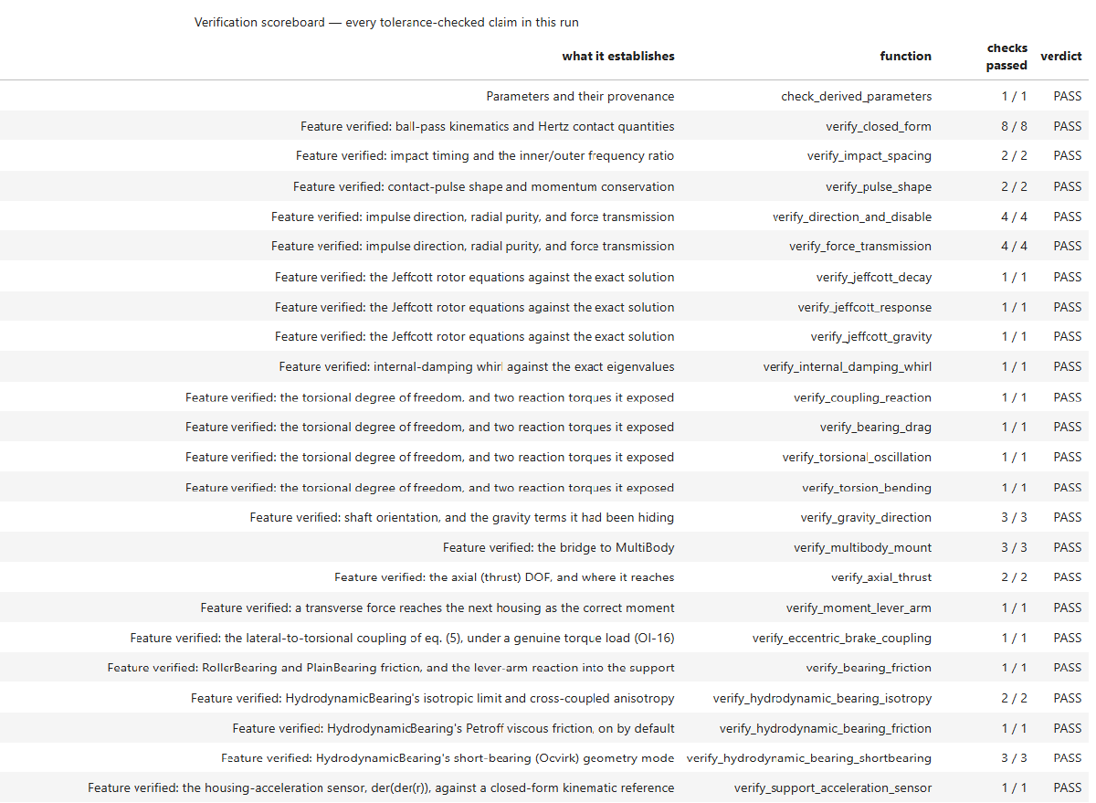
| Tolerance-checked checks in the latest run | 464 / 464 passed |
| Report sections with a recorded verdict | 81 |
| Test models in the library | ~90 |
| Claims in the evidence index | 150+, each with its own permanent id |
| Tolerances | fixed before the run, never adjusted to pass |
| Solver tier for evidence runs | 100× (or 10×) tighter than the production tolerance |
Verification: every feature against an independent reference
Each feature is compared with a closed-form or first-principles result that is computed independently in Python from the model’s inputs — never read back from the model’s own derived quantities. A selection:
| Feature | Checked against |
|---|---|
| Ball-pass kinematics, Hertz contact quantities | Closed-form bearing kinematics, to machine precision |
| Impact train during run-up | Phase-lock residual below 10⁻⁶ at every impact |
| Contact pulse | Momentum conservation, J = 2·m·v |
| Rotor lateral dynamics | Exact Jeffcott solution: free decay, unbalance response over 16 speeds (agreement 2·10⁻⁶), gravity superposition |
| Internal-damping whirl | Exact complex eigenvalues, with two control cases a merely dissipative model would fail |
| Torsional DOF | Two-inertia step response, and power balance of misaligned couplings |
| Gravity in any direction | Vector cantilever closed form with gravity rotated through the plane |
| MultiBody bridge | Imposed pose with an asymmetric tilt that catches swapped indices |
| Hydrodynamic bearing | Isotropic limit, cross-coupling, Petroff friction, Ocvirk short-bearing coefficients |
| Gear mesh | Load path, helical thrust and overturning moment, profile shift, contact-ratio attenuation, backlash dead zone, flank-friction power balance |
| Worm, hypoid, crossed-helical | Efficiency and self-locking threshold, published gear-set data at several shaft angles |
| Planetary stage | Kinematics, mesh phasing and cancellation, Love’s closed form for ring modes, sideband orders |
| Numerics | Tolerance study and output-resolution study for a ~16 µs contact pulse |
One point is not a validation. Any parameter a closed form depends on nonlinearly — a pressure, helix, spiral, shaft or contact angle, a ratio, an offset — is checked at several points across its validity domain, including the ends. A check at a single point can pass by coincidence: two errors that cancel there, or an identity that only holds there. The rule was adopted after a bevel-gear claim established at 90° met a task at 75°.
Validation: honest about what it is
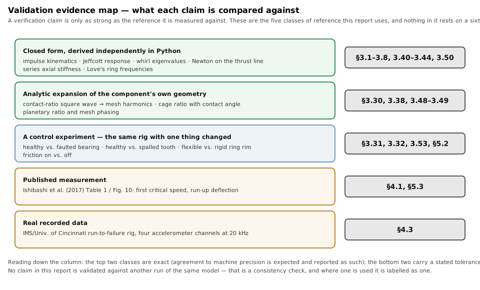
The report records what kind of reference every claim is checked against, so an aggregate count cannot overclaim. Of the claims in the evidence index, 78 % are checked against closed forms, 11 % against a second independent implementation, and the rest against conservation laws and published formulas. Two are validation claims against physical data — the published rotor-kit critical speed and the measured IMS accelerometer data. Both are valuable. Neither is the other.
The report’s credibility factor assessment follows SmartSE:
| Factor | Level |
|---|---|
| Verification | CL3 |
| People qualification | CL3 |
| Validation & UQ | CL2 |
| Process maturity | CL2 |
The overall level is set by the weakest factor. The report states plainly what holds it there: a single developer, no independent reviewer yet, and only a subset of features has been validated with real validation data. However, many values in gearboxes are hard or impossible to measure, and the code verification is extensive.
V&V that found real defects
Verification here is not a formality. Checks added after the frequency-domain results were already passing found defects those results could not see: a bearing model that generated a textbook impulse train but transmitted none of it to the shaft, a coupling that pumped energy into the lateral modes because it did not react its misalignment torque, a bearing that omitted the drag torque that motor-current signature analysis detects, and a shaft that — because it carried no dynamic mass — made every housing sensor blind to fault impulses. Each is documented, fixed and now guarded by a regression case.
Domain of applicability — including what is out of scope
| Area | Status |
|---|---|
| Lateral, torsional and axial vibration of shaft lines, bearings, housings, couplings and gearing | In scope |
| Labelled healthy/faulted synthetic data with known fault kinematics | In scope |
| Drive-train architecture: parallel, right-angle, crossed-axis and planetary gearing, thrust paths | In scope |
| Tooth-root and contact stress | Out of scope — use a gear rating standard or FE |
| Lubrication, thermal growth, wear evolution | Out of scope |
| Housing panel modes and structural dynamics above the pedestal | Out of scope |
| Absolute fault-signal amplitude, severity estimation, certification arguments | Not supported |
Knowing where a model stops is as much a part of its credibility as knowing where it works. Fault frequencies are kinematic and verified to machine precision; anything that depends on absolute fault amplitude inherits the validation level and uncertainty band stated in the report.
Evidence That Travels with the Model
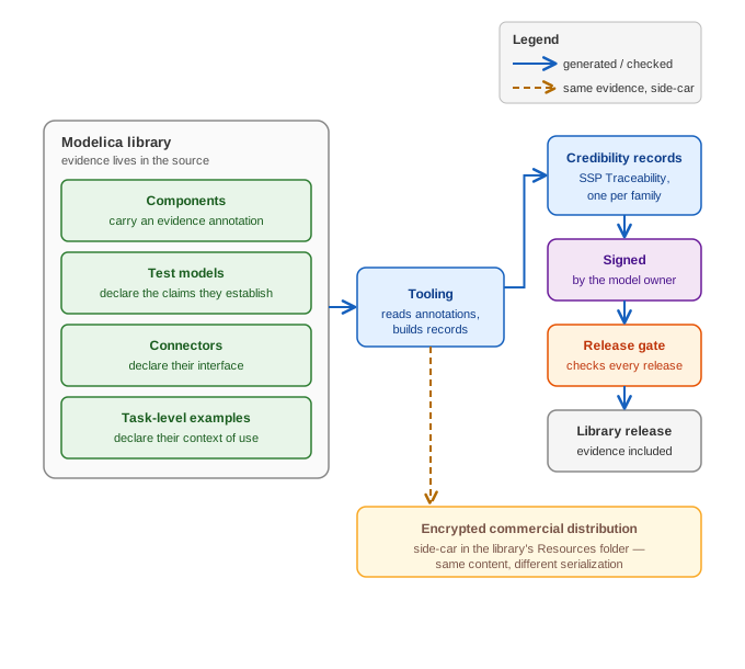
The credibility evidence is not a separate document that drifts out of date. It lives in the library itself: every component carries an evidence annotation, every test model declares which claims it establishes, every connector declares its interface, and task-level examples declare their context of use. From these, tooling generates machine-readable credibility records in the SSP Traceability format — one per component family — signed by the model owner and checked by a release gate before every release.
For commercial, encrypted distributions the same evidence is carried as a side-car in the
library’s Resources folder: same content, different serialization. We are working to bring this
library-evidence process into the next version of the SSP Traceability standard.
Built with AI Agents, Checked like Engineering
RotorDynamics was developed with AI coding agents working under explicit modeling and V&V rules. That changed the economics of verification: an agent can build and run every check an engineer thinks of, at a cost that no longer competes with the engineer’s own hours. The result is a library verified far more thoroughly than a hand-built library of the same size would typically be — and a credibility report that records exactly how, including the defects the process caught.
Tools and Requirements
- Modelica Standard Library 4.1.0
- Developed and verified in Modelon Impact (OCT compiler)
- Credibility report: Python,
modelon-impact-client, numpy / scipy / matplotlib - Regression testing against stored reference trajectories
- Export to FMI for use in digital-twin platforms
Reproducible in ten years: the report pins model file hashes, the git commit, the compiler and library versions and every experiment definition as a literal. Re-running the notebook end to end regenerates every result.
Resources
| Resource | Link |
|---|---|
| Source paper for the bearing-fault model | Ishibashi, Han, Kawai, Modelica Conference 2017 |
| Credibility report (PDF) | on request |
| Consulting: digital twins and synthetic data | modelbased.cloud/services/consulting |
| Modelica training | modelbased.cloud/services/training |
| Contact / get a quote | Schedule an appointment |
| Developer and vendor | Model Based Innovation LLC |
Interested in synthetic fault data for your machines, or in a credible digital twin of a drivetrain?